DIODE RECEIVER
Receive HF, VHF, UHF data signals for analysis using a Ge Diode
Detect RF carrier switching with a germanium diode and an oscilloscope.
You want to hack a radio device to drive it from your microcontroller. You need to decode the radio signal but you don't have a receiver. Try using a Germanium diode to connect to your scope.
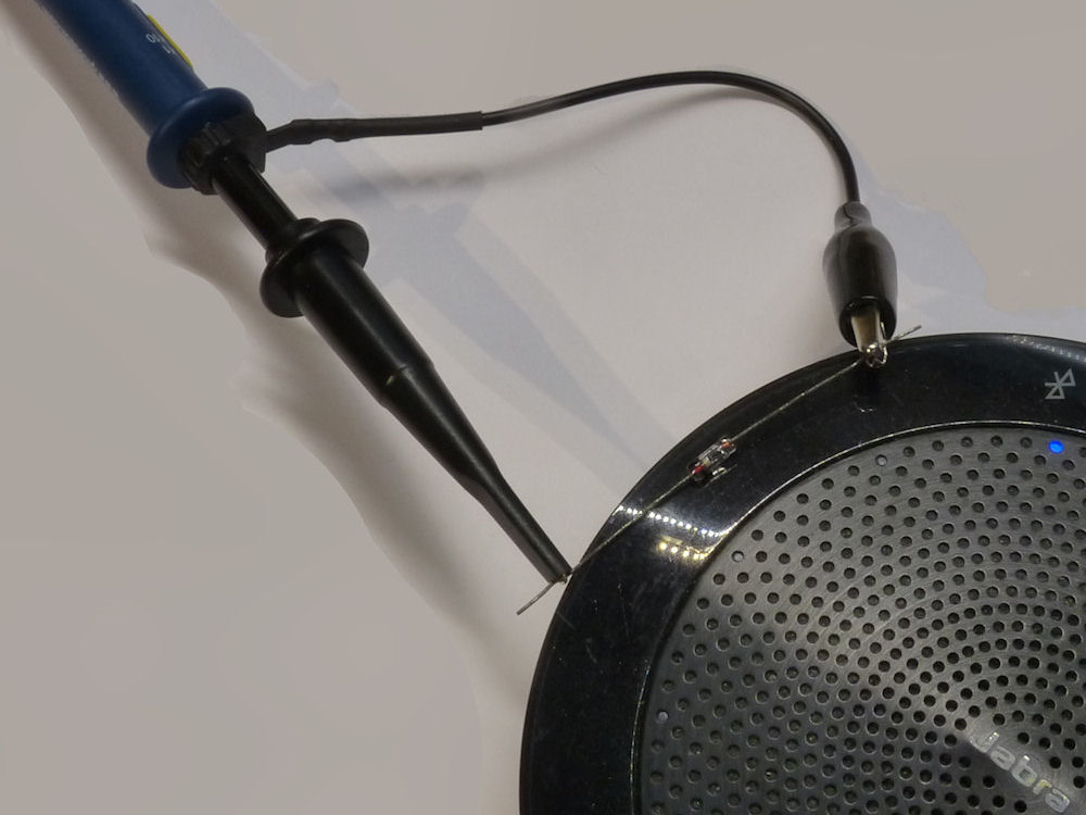
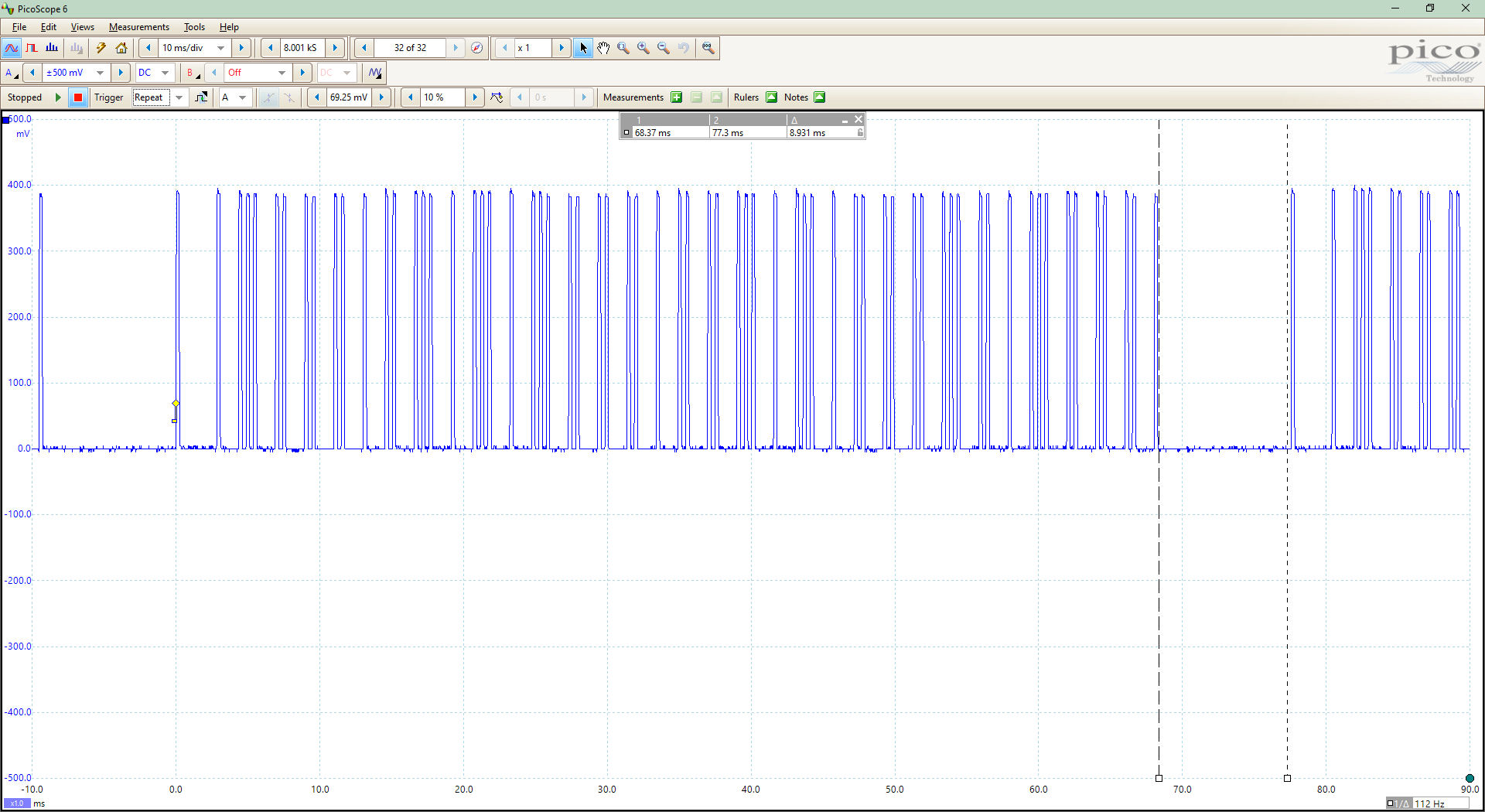
Connect the diode to your oscilloscope probe and hold the diode close to the transmitter. With the black marking to the probe tip you get a positive signal when the transmitter carrier is on. The picture above shows an OA91 diode, the 'scope is a PicoScope 2204A, and the output is shown in the PicoScope KlikAanKlikUit Signal picture.
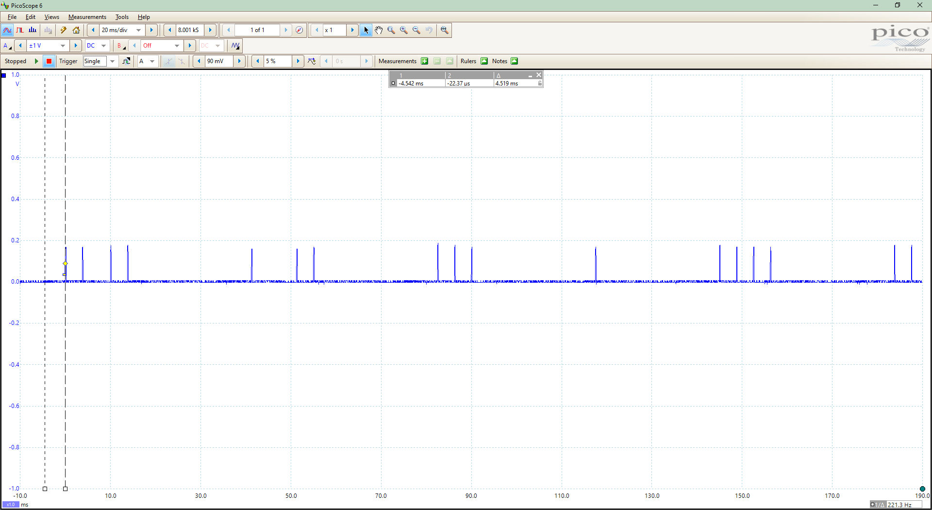
This works over a wide range of frequencies, the KlikAanKlikUit transmitter operates at 433 MHz and I have detected signals in the 2.4 GHz band, see the Bluetooth Detection picture (see Note 6 below).
Notes:
- Once you have collected the data from your device it has to be decoded. I will be adding an article about how to do that at some time, (if it is important to you email me) where I show how to dump the signals from the PicoScope to a PC, and automatically analyse switch commands in MS Excel.
- The diode I use is type OA91, you can just to say see the markings on the photo below, "91" in the upper picture and "OA" in the lower picture. They are not easy to come by, probably not made anymore. You could look in 1970s radios and similar from recycling shops (or look on ebay and the like?).
- The diode must be placed (very) close to the transmitter. You may have to move the diode around the outside of the device to locate the optimal position for detecting the signal. The PicoScope traces were obtained with the diode positioned as in the photos at the top of the page.
- This method does not work with silicon, or Schottky diodes.
- The oscilloscope is a PicoScope 2204A USB oscilloscope. Inexpensive (to my mind), it cost around 149 currency units but invaluable for debugging any hardware projects. The software makes it immensely powerful as you can dump waveforms as csv data. See the link in "1" above.
- I have not decoded any 2.4 GHz signals but, the method can be used to see if a WiFi or Bluetooth device is transmitting. The Bluetooth Detection picture was made monitoring VLC player on a phone using a Jabra 510 speaker as output. It was easy to see the difference between when VLC was playing, pulses as in the picture, and VLC was stopped, a flat trace.
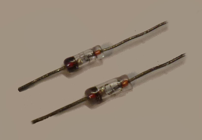
on the upper one and "OA" on lower one.
Have fun,
Andy