THE MCU AUTOPOWER CIRCUIT
Autocontrol microcontroller battery power includes schematic, and component value calculation
What it does:
This circuit shuts off the power to a microcomputer, MCU, when it is not in use. It is the ideal power control solution for battery powered devices that run for short periods of time, e.g. IR remote, calculator, data entry device, and datalogger.
The device is turned on manually by a push button, or automatically by a logic HIGH wake up signal.
When the Microcomputer Unit, MCU, first starts up it raises a pin to hold power on; when it has finished its tasks it lowers the pin, the power circuit shuts off and the MCU waits to be started again. Current drain when off is less than 1 micro amp, much less than when a MCU is just put into sleep mode.
The video above shows the circuit in operation. Two runs are shown: firstly, after pressing the button the LED flashes for ten seconds and the device shuts itself down. In the second run the flashing is started and then interrupted by a second button press that cancels the run under the control of the MCU.
Where I used it:
I use a TV as a monitor for my PC but, when I power it on using the TV remote I have to wait ten seconds for the TV to start up before I can select the PC in the AV mode. I wanted a box with one button to press that would start the TV and select the AV mode without me having to wait.
The Infra-Red controller that I made worked fine but had a power drain of about 40mA. When it was off it drained the battery in two days. I wanted to reduce this current as much as possible and with the autopower circuit the Li‑ion rechargeable lasts for months between charges.
Use Cases:
This circuit is useful where:
- The device is using battery power.
- The device must consume a minimum of power when not in use.
- The device can be powered down while not used. Either:
- it does not need to remember a state between uses, for example a TV remote control, or
- it saves its state to memory so that it can continue from where it left off when it was powered down, for example a parking meter.
- The device can (be allowed to) stop itself automatically.
The Circuit:
This article describes the basic idea and shows schematics for an Arduino Uno version operating at 12V for the Arduino Uno coaxial 12V power input. Other versions have been made, for example, to control the Adafruit ItsyBitsy at nominally 3.7 V battery power.
The Generic Autopower Schematic
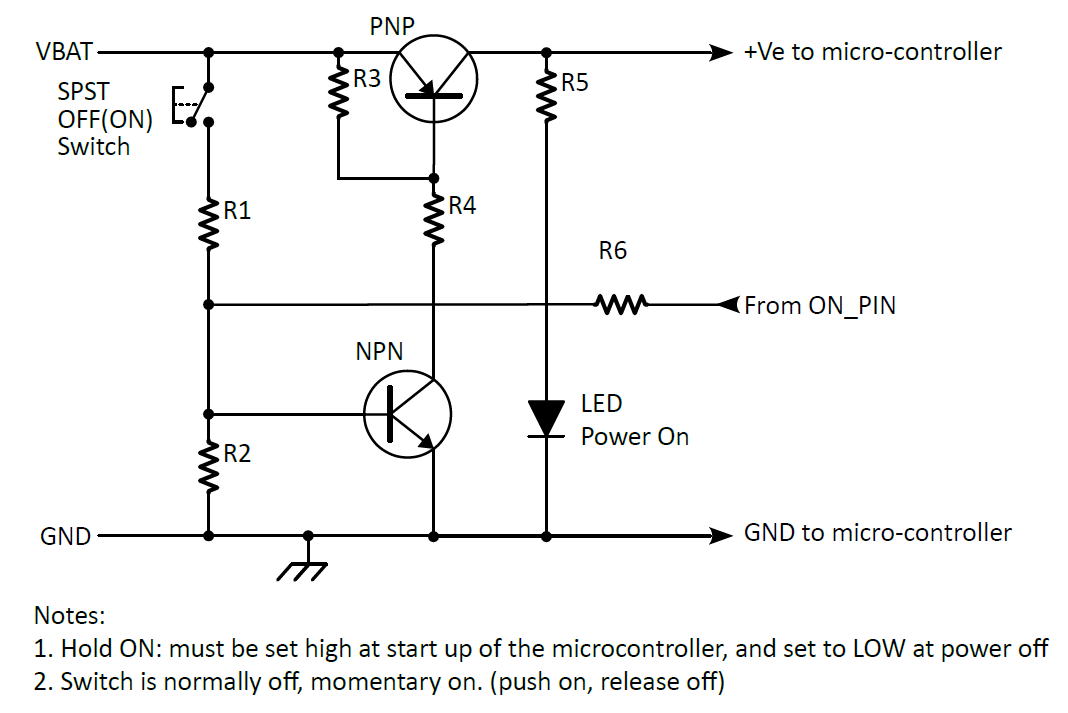
There is a constant voltage at VBAT but both transistors are off so no current (< 1 µA) can flow to the microcontroller board. When the push button is pressed a current, limited by R1, flows into the base of the NPN transistor. The transistor turns on and pulls a current through R4 from the base of the PNP transistor. The microcontroller starts up and sets ON_PIN HIGH. The current from the ON_PIN through R6 keeps TR1 turned on until the microcontroller sets ON_PIN LOW. Both transistors turn off and are held off by R2 and R3.
Arduino Uno Autopower Schematic
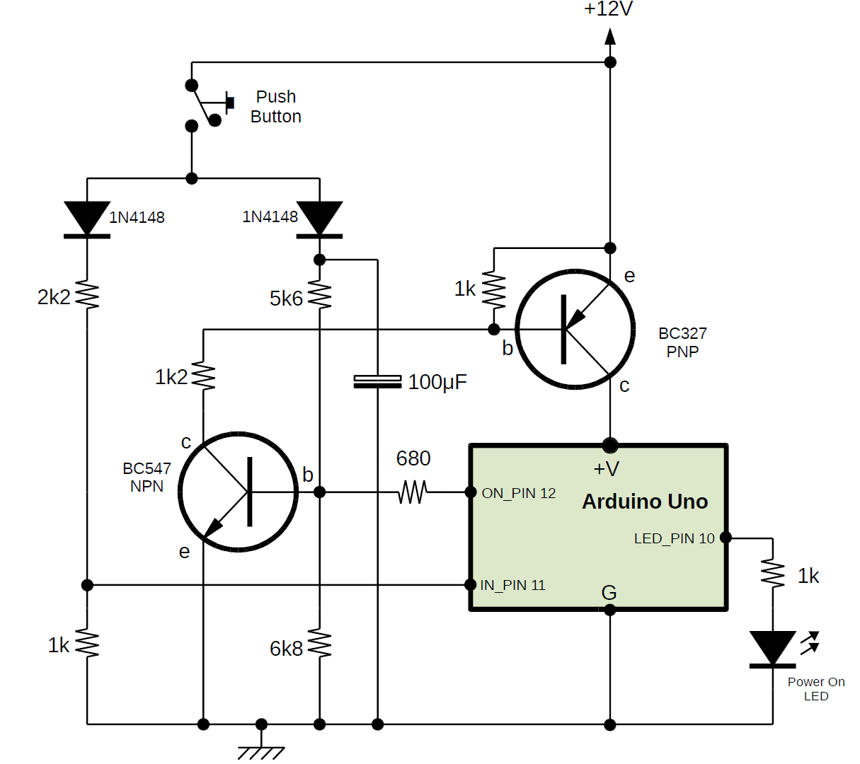
The autopower schematic for the Arduino UNO shows the working component values for the breadboard shown in the video.
When the Push Button (SW1) is pressed current flows through R4 into the base of TR1 turning it on and pulling current through R4 from the base of TR2. The current from the base of TR2 turns TR2 on and powers up the Arduino Uno. The first thing that the Arduino does in the “setup” function is to set the ON_PIN as an output and to set it HIGH. The current from the ON_PIN flows into the base of TR1 via R6 taking over from the Push Button and holding the power circuit on until, at the end of the program run the ON_PIN is turned off/LOW setting the power circuit into standby and the program goes into a while (true) {} loop.
The Arduino Uno is fairly slow at starting up. The capacitor C1 had to be added to the circuit to provide a delay of about 1.5 seconds to give the ON_PIN time to be turned on. When the button is pressed C1 charges to around 11.3 V and discharges slowly via R4. I haven’t found C1 necessary for other MCUs that I have used, e.g. Adafruit ItsyBitsy and Feathers, they seem to start up quicker.
Use of the IN_PIN is optional. It senses the state of the push button and can provide additional functions. For example, I have used it as an abort signal. One press starts the system, a second press during operation signals a forced shutdown.
Calculating Circuit Values
From left to right, see the Arduino schematic:
IN_PIN
When the button is pressed current flows from the 12 V PSU into D1 and down the chain R1 and R2.
R1 and R2 form a potential divider to drop the 12 volt supply to under 5 volts to provide a safe logic 1 (HIGH) at the IN_PIN input of the Arduino.
The voltage at the IN_PIN is:
(VPSU – DiodeVdrop) * R2/(R1 + R2)
(12 – 0.6) * 1000/(2200 + 1000) = 3.6 V
When the switch is open R2 holds the IN_PIN LOW.
The critical thing in this part of the circuit is that the IN_PIN must never see more than 5 V otherwise the Arduino Uno could be damaged. The voltage drop in the diode and the resistor values are chosen so that the IN_PIN high voltage (~3.6 V) is a good logic 1 (>2 V) but less than 5 V.
D1 and D2 provide isolation between the IN_PIN circuit and the ON_PIN circuit. Without D2 current could flow from the ON_PIN towards the IN_PIN operating it without pressing the switch. D1 is not strictly necessary.
Power control using TR1 and TR2, and the ON_PIN
Assuming that the circuit needs to be able to supply say 200 mA through the BC327 and assuming a DC current gain hFE of say >=100 (take a look at the data sheet) the current needed into the base of TR2 is at least 2 mA, and the current into TR1 should be a minimum of roughly 0.02 mA. These are the minimum values, to allow for low hFE parts and to ensure that the transistors are saturated (switch fully on) the actual design values will be higher.
Let’s start at the base of TR1. When TR1 is on there will be roughly 0.6 V (a diode forward voltage drop) between the base and emitter.
When SW1 is closed R4 limits the current into the base of TR1 which will be:
((VPSU – DiodeVdrop – VBE)/R4) – current through R5 = ((12 – 0.6 – 0.6)/5600) – 0.00009 = 2 mA (ish)
The current through R5 will be the (base emitter voltage)/R5 = 0.6/R5 = 0.6/6800 = 0.09 mA. The purpose of R5 is to ensure that TR1 is firmly off when there is no base current. It has little influence in the TR1 on state.
When the ON_PIN is HIGH at say 4.5 V the current into R6 will be:
(voltage across R6)/R6 = ((ON_PIN voltage) – (TR1 base emitter voltage))/R6
(4.5 – 0.6)/680 = 6 mA (ish)
Either of these, the current from the switch or from the ON_PIN, is capable of saturating TR1 to switch on TR2.
The current through R3 when TR1 is on is
((VPSU – TR2 VBE – TR1 VCE)/R3) – (current through R7) = ((12 – 0.6 – 1.0)/1200) – 0.0006 = 8 mA (ish)
R7 current = (TR2 base emitter voltage)/R7 = VBE /R7 = 0.6/1000 = 0.6 mA.
Plenty to saturate TR2
Bear in mind that these values will need to be adjusted for other MCUs when operating at other supply and logic voltages. The Arduino Uno has 12 V power and 5 V logic, a 3 V ItsyBitsy will have 3.3 V power and 3 V logic. The calculations need to be adjusted to cope with that.